Designing a 56 g flying wing at Reynolds 40,000
A design write-up: HULL-4, a 520 mm-span micro flying wing sized around a salvaged 29×24 mm mainboard, four 6×15 mm coreless motors, and a 750 mAh 1S battery. Not yet built or flown — the whole aircraft is designed to weigh less than a slice of bread, and at that scale the usual aerodynamics stop applying.
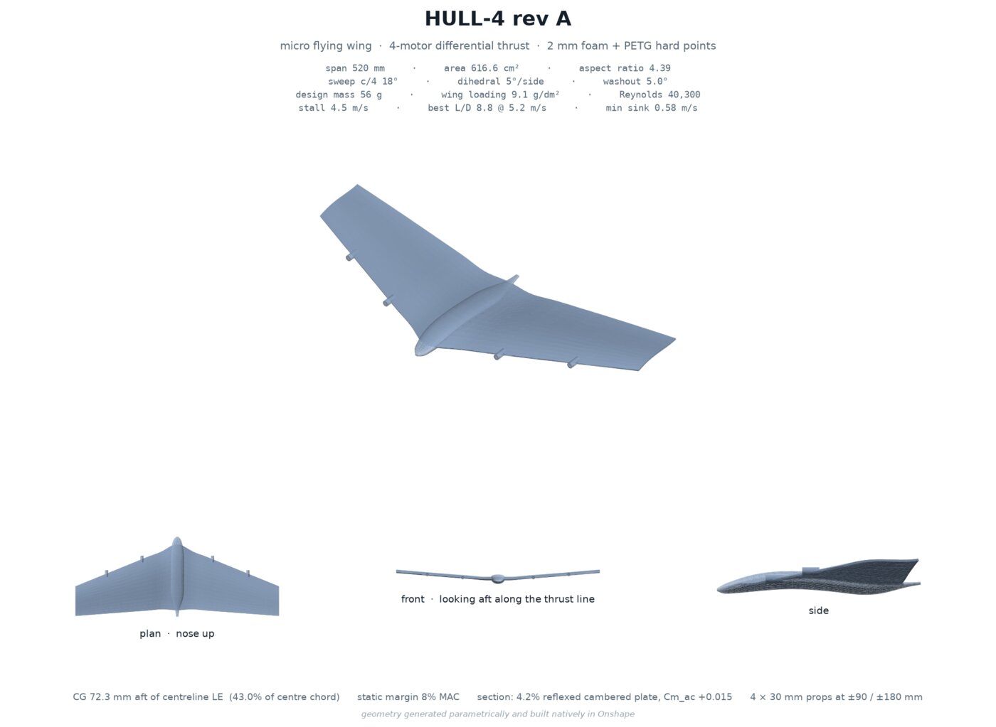
Flying at insect scale
A 520 mm span at 5 m/s cruise gives a mean chord around 120 mm and a Reynolds number at the wing of about 40,300. Full-size gliders operate in the millions. A typical foam-board park flyer with a decent brushless motor sits in the low hundreds of thousands. Forty thousand is a step further down again — the regime large dragonflies and small bats fly in, and one most small-airplane aerodynamics references don't cover.
A thick, rounded aerofoil — the shape most people draw when asked to sketch a wing — tends to trip up below about Reynolds 100,000: the flow separates near the leading edge, fails to reattach, and drag climbs fast. HULL-4 uses a thin, reflexed cambered plate instead: 2.7% thick, with the camber line built up to 4.2% of chord (two different numbers describing the same cross-section — thickness and camber aren't the same axis, and mixing them up is an easy way to misread this kind of spec sheet). 2 mm foam board rolled over a tube happens to hold roughly that curve on its own, so the material's default shape and the aerodynamic target didn't need to fight each other.
Aspect ratio, spent where it actually helps
A longer, narrower wing is supposed to fly better — less induced drag, better glide. Run the numbers for this airframe and the payoff barely shows up: L/D moves from about 8.6 to 8.9 across aspect ratios 4 through 8, because induced drag isn't the term that dominates at this Reynolds number. What a narrower wing does instead is shrink the root chord, which drags the local Reynolds number down further — into territory where the thin-plate section behaves less predictably — and leaves less physical room for the battery and mainboard. HULL-4 settled on aspect ratio 4.39, low by full-size standards, trading a rounding error's worth of glide performance for Reynolds margin and internal volume it needed.
Sweep, set by a balance calculation
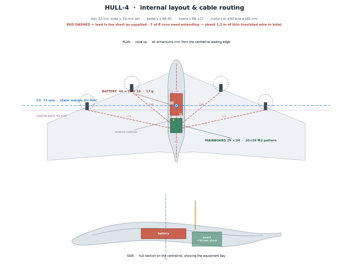
HULL-4 has no tail, so sweep is the only lever available to move the wing's aerodynamic center relative to a center of gravity already pinned down by where the battery and motors physically sit. The target was a 7.3% static margin — roughly, how strongly the aircraft self-corrects after a gust — with four motor nacelles, the battery, and the mainboard packed wherever they fit. 18° of sweep at the quarter-chord is what lands the CG and the neutral point in that relationship for this specific hardware layout, read off a balance calculation rather than chosen by eye.
Washout, and how close to the edge it sits
Sweep buys a second problem on a tailless wing: swept wings stall at the tips first, and on a swept-back wing that tip stall pitches the nose up — the wrong direction, since the pilot's instinct is to pull back harder. Washout counters it by twisting the tip to a lower angle of attack than the root, so the root stalls first instead.
The angle came from a lifting-line model — a custom Python implementation, checked first against the known analytic solution for an elliptic wing to four decimal places before it was trusted on this geometry — swept across a range of washout angles. At 0°, the wing stalls at 68% span with a negative stability margin: a real tip stall. At 5°, the stall point moves to 37% span with margin in hand. Past about 6.5°, the failure mode flips and the root starts stalling too early instead. 5° isn't centered in that range — it sits closer to the 6.5° edge than to 0° — which is presumably why the build manual states it twice, once in the parts list and again in the assembly steps, rather than leaving it as a suggestion.
The one number nobody measured yet
The whole airframe is sized around an assumed thrust of 9 g per motor, taken from the motor's datasheet-adjacent numbers and never actually put on a scale. The design is explicit about how much that assumption matters: at 30 g of total static thrust the aircraft as sized is not expected to sustain flight, and at 48 g it climbs twice as well as at the design point. Before cutting any foam, the cheapest check available is taping one motor and prop to a kitchen scale at full throttle and reading the number off it — wing loading, stall speed, and the mass budget all inherit whatever error that one reading carries.